Collection: Logic Analysers
The Debug Store offers a diverse range of logic analyzers from various manufacturers, including Acute Technology, Saleae, ZeroPlus, and Janatek. These devices feature different channel counts, sampling rates, and memory depths to suit various debugging needs. Options include USB-based portable units and more advanced models with high-speed timing and state analysis capabilities for professional use.
-
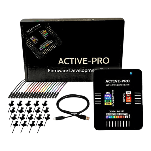
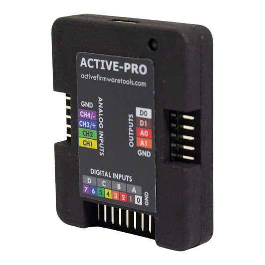
Active-Pro Firmware Debugger
Vendor:Active Firmware ToolsRegular price£658.80 inc VAT£549.00 exc VATRegular priceUnit price per -
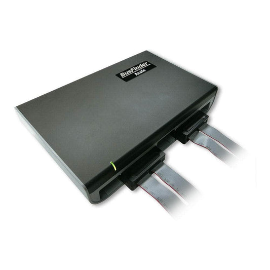
Acute BusFinder BF6264 Pro Protocol Analyser
Vendor:Acute Technology, IncRegular price£13,800.00 inc VAT£11,500.00 exc VATRegular priceUnit price per -
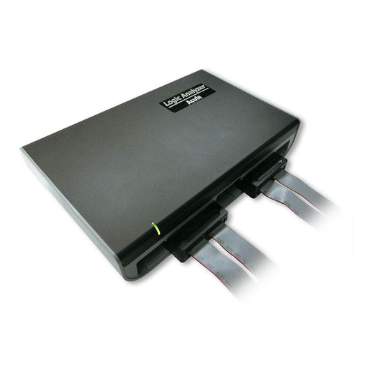
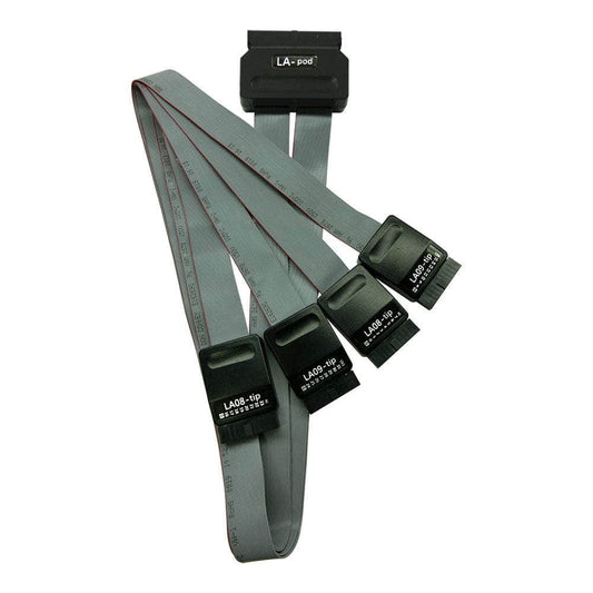
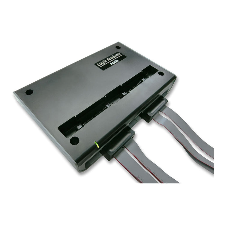
Acute Technology LA4000 Series 68/136 Ch Logic Analyser
Vendor:Acute Technology, IncRegular price£8,520.00 inc VAT£7,100.00 exc VATRegular priceUnit price per -
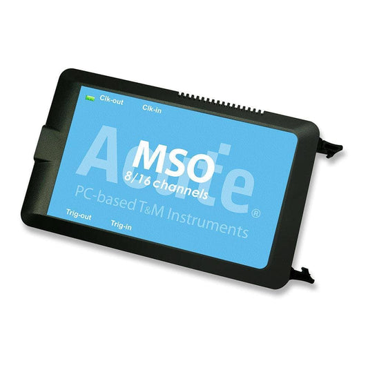
Acute Technology MSO2008E 8-Channel MSO (Analog or Digital)
Vendor:Acute Technology, IncRegular price£1,358.40 inc VAT£1,132.00 exc VATRegular priceUnit price per -
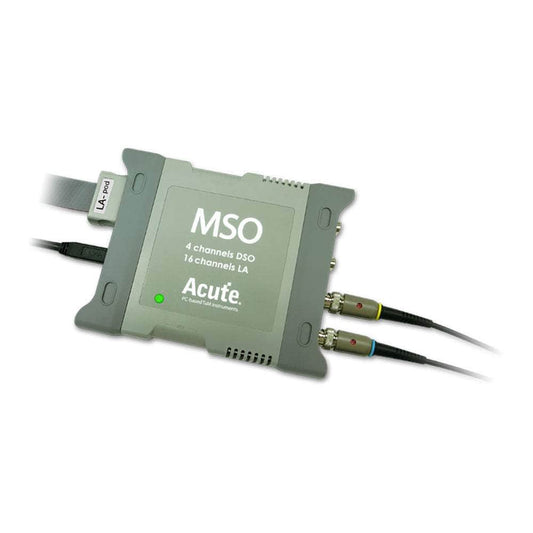
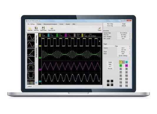
Acute Technology MSO3124E Mixed-Signal Oscilloscope - 6-in-1 Instrument | 200MHz | USB-Powered
Vendor:Acute Technology, IncRegular price£2,490.00 inc VAT£2,075.00 exc VATRegular priceUnit price per -
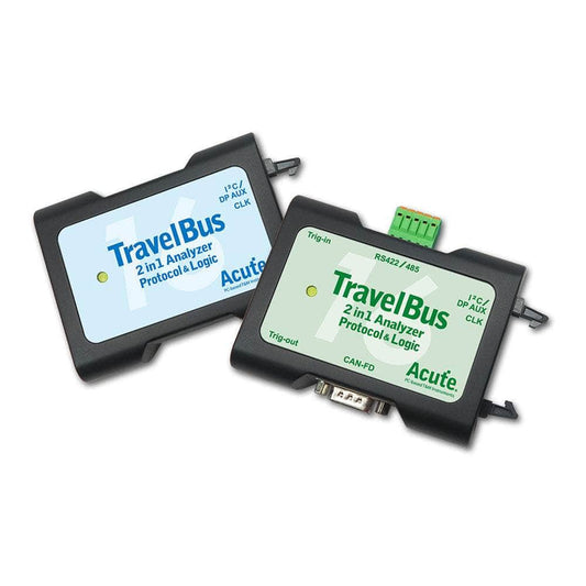
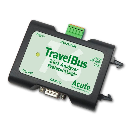
Acute Technology TravelBus TB3000 Series Logic Analyser
Vendor:Acute Technology, IncRegular price£220.56 inc VAT£183.96 exc VATRegular priceUnit price per -
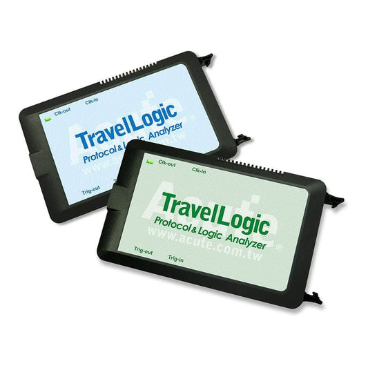
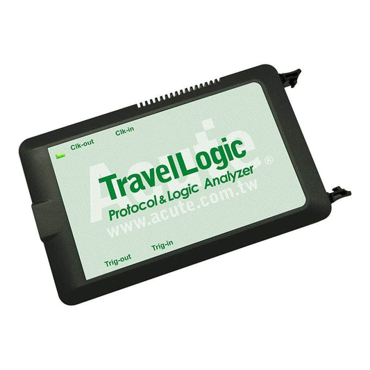
Acute Technology TravelLogic 34-Channel Logic Analyser
Vendor:Acute Technology, IncRegular price£1,393.85 inc VAT£1,161.65 exc VATRegular priceUnit price per -
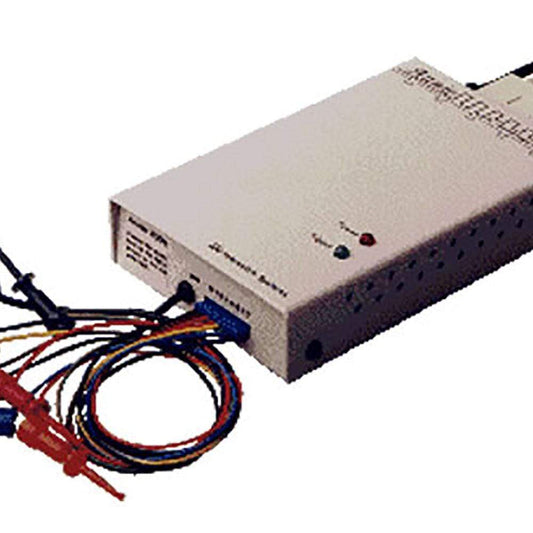
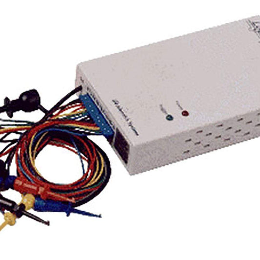
Janatek Annie-200P Logic Analyser
Vendor:JanatekRegular price£125.30 inc VAT£104.50 exc VATRegular priceUnit price per£295.00 GBPSale price£125.30 inc VAT£104.50 exc VATSale -
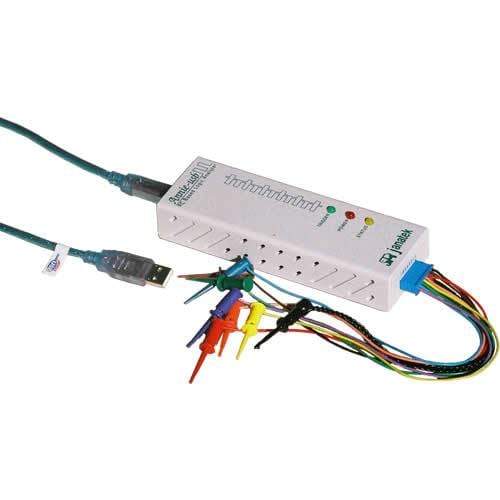
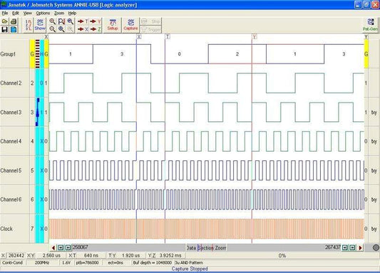
Janatek Annie-USB 8-Channel Logic Analyser
Vendor:JanatekRegular price£98.90 inc VAT£82.50 exc VATRegular priceUnit price per£175.00 GBPSale price£98.90 inc VAT£82.50 exc VATSale -
Janatek Logic-3P Logic Analyser
Vendor:JanatekRegular price£72.50 inc VAT£60.50 exc VATRegular priceUnit price per£175.00 GBPSale price£72.50 inc VAT£60.50 exc VATSale -
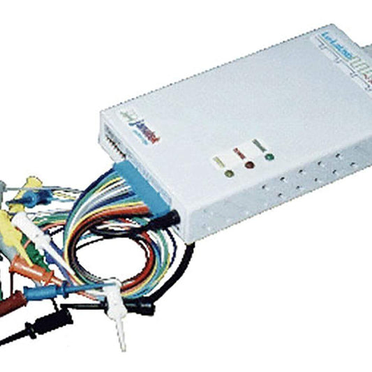
Janatek LuLaUSB Logic Analyser
Vendor:JanatekRegular price£125.30 inc VAT£104.50 exc VATRegular priceUnit price per£430.00 GBPSale price£125.30 inc VAT£104.50 exc VATSale -
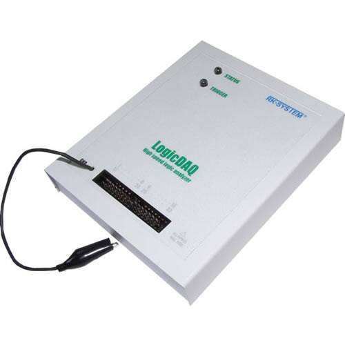
RK-System LogicDAQ Logic Analyser
Vendor:RK-SystemRegular price£417.94 inc VAT£348.34 exc VATRegular priceUnit price per£450.00 GBPSale price£417.94 inc VAT£348.34 exc VATSale -
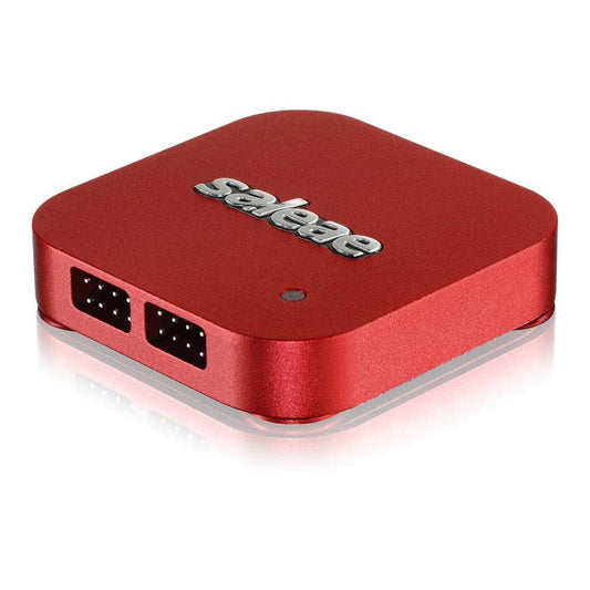
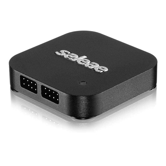
Saleae Logic 8 Logic/Analogue Analyser
Vendor:Saleae, IncRegular price£486.00 inc VAT£405.00 exc VATRegular priceUnit price per -
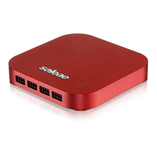
Saleae Logic Pro 16 Logic/Analogue Analyser
Vendor:Saleae, IncRegular price£1,494.00 inc VAT£1,245.00 exc VATRegular priceUnit price per -
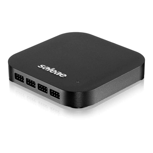
Saleae Logic Pro 8 Logic/Analogue Analyser
Vendor:Saleae, IncRegular price£996.00 inc VAT£830.00 exc VATRegular priceUnit price per -
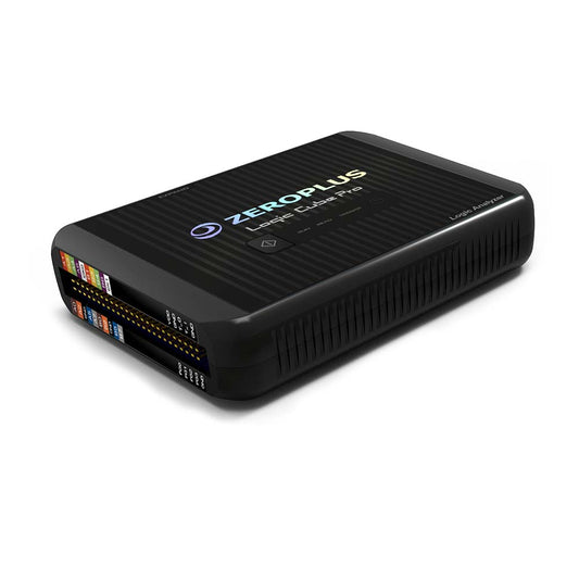
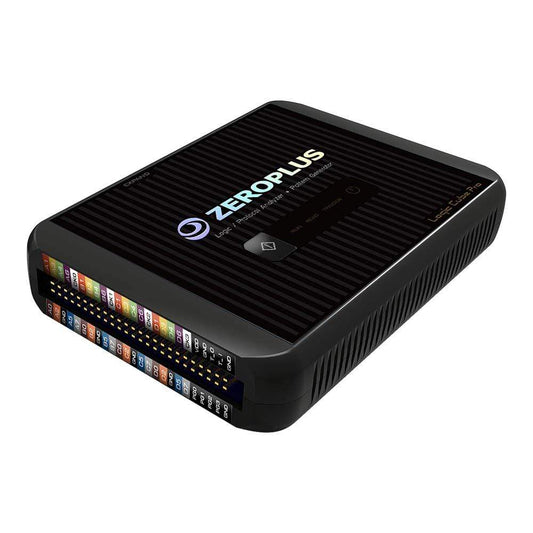
ZeroPlus LAP-C Pro Series Logic Analyser
Vendor:ZeroPlus Technology Co LtdRegular price£1,110.00 inc VAT£925.00 exc VATRegular priceUnit price per